Pin Diodes Are Used in Which Frequency Range
Figure-2 depicts PIN diode used as RF switch in series and shunt configurations. PIN diode is a diode with a wide and undoped intrinsic semiconductor region between a p-type an n-type semiconductor region.
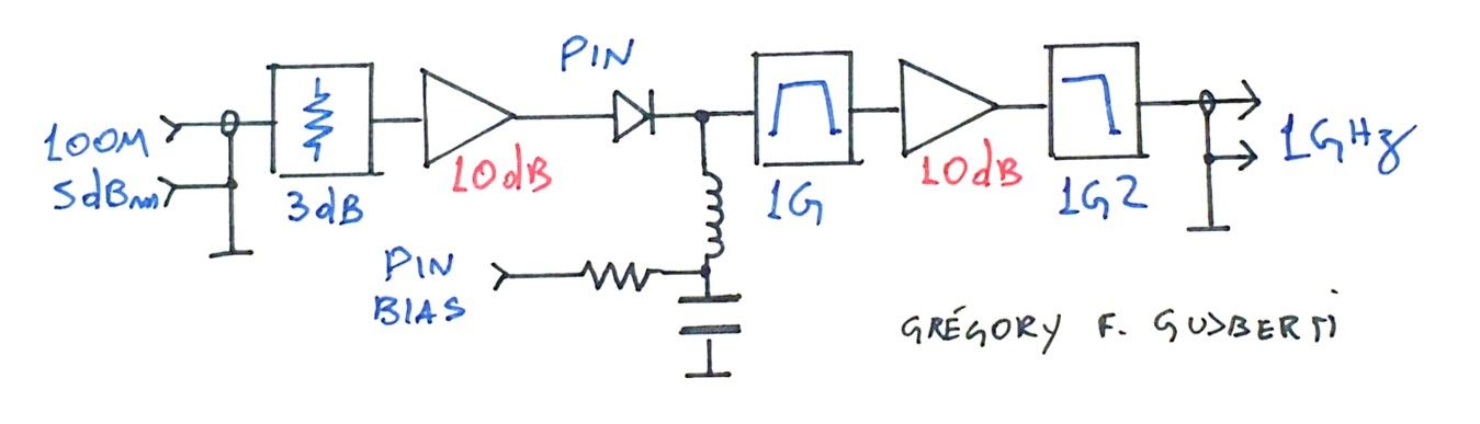
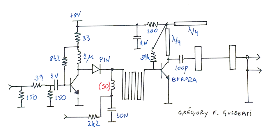
Frequency Multiplier With Pin Diode
When the control current is varied continuously the PIN diode is useful for leveling and amplitude modulating an.
. I dont remember the bandwidth of the preselector that we were able to achieve but it was tunable over a range of 130-180 MHz or so. By carefully selecting diodes you can make a PIN diode switches operate down to 1 MHz. Depends on how high is the frequency.
The PIN diode is a current-controlled resistor at radio and microwave frequencies. The practical low resistance limitations result from package parasitic inductances and junction contact resistances both of which are. PIN diodes are widely used in the design of SPST and SPDT switches.
Learn more at BYJUS. When we deal with 1500 MHz we usually use surface mount 0603. PIN diodes are low-cost low-.
1 Ω to 10 kΩ through the use of a DC or low frequency control current. Because of the frequency limitations of common test equipment capacitance measurements are generally made at 1 MHz. Design used over the instantaneous frequency range from 10 MHz to beyond 2 GHz is the PI network.
When the control current is varied continuously the PIN diode is. Thicker diodes can be used as switches to lower frequencies. Other wise there are significant.
This high-frequency resistance may vary over a wide range from 01 Ω to 10 kΩ in some cases. 25dB Switching Time up to 150ns Silicon Dioxide Passivated Chip PIN Diodes APITechs series of passivated PIN diode chips have an optimally tailored profile and sputtered gold metallisation. At frequencies much lower than f τ the capacitance characteristic of the PIN diode resembles a varactor diode.
When the PIN diode is forward biased holes. If you operate pin diode above its specified frequency range then you need to practically Realize its RLC property and implement same in your simulation model. PIN diodes in RF switch applications PIN diode SPST switches Figure 9 Output return loss of PIN diode SPST switch with BAR63-02L in on state I bias 98 mA Figure 10 Isolation of PIN diode SPST switch with BAR63-02L in off state I bias 0 A 300 600 900 1200 1500 Frequency MHz-50-40-30-20-10 0 868 MHz-2707 dB 434 MHz-3765 dB BAR63-02L.
In a variety of microwave applications it was also used but it took until around 1960 before its use in this application became more widespread. The useful range is smaller though. The benefit of this design is its broadband constant impedance wide dynamic range and good compatibility with AGC signals.
The response of the attenuator was measured between 13 GHz and 26 GHz. The Skyworks APD series of silicon PIN diodes are designed for use as switch and attenuator devices in high-performance RF and microwave circuits. The wide intrinsic region also means the diode will have a low capacitance when reverse-biased.
58 views View upvotes Promoted by Masterworks. Gies PIN diodes are in the range of 002 to 2 pF depending on the diode design. The PIN diode was first used as a low-frequency high-power rectifier in 1952.
As shown in the figure-2 shunt mounted diode produces higher isolation values across wider frequency range. If youre dealing with more like 100 MHz a normal leaded resistor will usually do. In a PIN diode the depletion region exists almost completely within the intrinsic region.
A product I worked on earlier in my career was a narrowband receiver with a preselection bandpass filter whose center frequency was tunable by applying differing DC voltages to a pair of PIN diodes. Our PIN LIM Step Recovery Tuning Varactor microwave diodes provide broadband peRFormance from 1 MHz to 20 GHz in ceramic packages ideal for switching attenuator and control applications. The PIN diode is used as a current-controlled resistance component in the PI network.
Our years of robust heritage coupled with our skilled design and production staff provides OEM companies with high quality custom microwave semiconductor products. Using an intrinsic section can considerably increase the breakdown voltage for the case of high-voltage. The PIN diode designs are useful over a wide range of frequencies from below 100 MHz to beyond 20 GHz.
After the PN-combination diode was constructed in the year 1940s the diode was first used as a high-energy rectifier low-frequency during the year 1952. Examples for this frequency range are the UM2100 series devices. PIN switch diodes are optimized for switching appli-cations where low resistance at low current combined with low capacitance is required.
Low junction capacitance of the PIN diode chip combined with ultra-low package parasitics mean that these prod-ucts may be used at frequencies which are higher than the upper limit for conventional PIN diodes. However at microwave frequencies its IV curve changes and it functions as a current-controlled resistor with the resistance value set by the level of DC current. It was first used in 1952 as a low frequency high power rectifier.
When it gets to more like 5000 MHz we might use something smaller like 0402 or 0201 I hate them theyre too small. A PIN diode functions as a conventional diode rectifier at low frequencies. Frequency range of 01GHz-120 GHz Isolation.
The results obtained from Equation 3 are valid over an extremely broad frequency range when Microsemi PIN diodes are used in a circuit. In this application PIN diode can be biased to either a low or high impedance state. The PIN diode is an alteration of the PN-combination for special systems.
The frequency at which the PIN diode transitions from acting like a diode to acting like a resistor is a function of the thickness of the I-region. It is a silicon semiconductor diode in which a high-resistivity intrinsic I region is sandwiched between a P-type and N-type region. 11 rows Pin diode FET Hybrid.
The PIN diode is the fact that it can under certain circumstances behave as an almost pure resis-tance at RF frequencies with a resistance value that can be varied over a range of approximately 1 Ω to 10 K Ω through the use of a DC or low frequency control current. We describe a simple PIN diode controlled variable attenuator that employs a 0-dB branch line directional coupler.

P6ke180a Tvs Diode Diode Diodes Semiconductors

Pin On Tools

Time To Source Smarter Diodes Electronics Components Home Automation System
Frequency Multiplier With Pin Diode

1n5817 Schottky Diode Diode Electronics Components Diodes

Crystal Radio Diode Radio Transistor Radio Diode
Two Diode Odd Order Frequency Multipliers

1n5822 Schottky Diode Diode Diodes Data Sheets

Pin On All About Swr Du1ec Homeproject

Diode Identification Diy Electronics Electronics Basics Electronics Circuit

Crystal Radio Diode Radio Diode Shortwave Radio
Diode Types Of Diodes Electronics Basics Rohm
Diode Types Of Diodes Electronics Basics Rohm

Eravant Modular Amplifiers Versus Bench Top Amplifiers Led Diodes Transmission Line Modular

Radio For Aviation Frequencies Funny And Simple Radio Old Computers Funny

Pin On Products

Pin On Electronics Circuits

Pin Diode High Frequency Equivalent Circuit Download Scientific Diagram

Light To Frequency Converter Tsl235r Arduino Light Sensor Light Sensors Arduino


Comments
Post a Comment